High-Speed Pluggable Optical Transceivers (OSFP / QSFP-DD) and Fiber Hygiene
Plain-English definition
High-bandwidth optical modules (such as 400G/800G OSFP and QSFP-DD) converting electrical switch/GPU signals into laser light across multi-fiber MPO/MTP or duplex LC patch cords, requiring strict end-face cleanliness, minimum bend radius, and air-cooling margin.
Why it matters on shift
High-speed AI optics dissipate 15 W to 30 W per pluggable module, creating residual air-cooling demand even inside liquid-cooled racks, while a microscopic dust speck on an uninspected MPO ferrule drops multi-node training jobs.
Illustrative operational example
In an illustrative 100 kW liquid-cooled AI rack where cold plates capture 80% of server heat, sixty-four 800G OSFP transceivers and VRM fans still reject 20 kW into hall air, requiring active rear-door or CRAH cooling.
Scope, code & safety boundary
Never look directly into uncapped fiber connectors or active transceivers (invisible Class 1/1M infrared laser hazard), always inspect and dry-clean ferrules before mating, and avoid pinching fiber slack in rear rack doors.
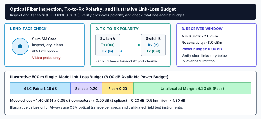
Reliable optical links require clean 9 micrometer cores verified with a video probe (IEC 61300-3-35), crossover polarity connecting each transmitter (Tx) to the far-end receiver (Rx), and total connector, splice, and cable loss within the transceiver power budget.
Read plain-text walkthrough of this diagram
Three-stage optical check plus stacked loss bar. Stage 1 shows a 9 micrometer single-mode fiber core inspected, dry-cleaned, and re-inspected with a digital video probe only (never an unfiltered eye scope). Stage 2 shows Switch A Tx feeding Switch B Rx and Switch B Tx feeding Switch A Rx. Stage 3 shows an illustrative 6.00 dB power budget (-2.0 dBm minimum launch minus -8.0 dBm receiver sensitivity) with a reminder to verify receiver overload limits on short links. Bottom bar sums 4 mated LC connector pairs (1.40 dB), 2 fusion splices (0.20 dB), and 0.5 km single-mode fiber (0.20 dB) to 1.80 dB modeled loss, leaving 4.20 dB unallocated margin.
Related courses & interactive lab practice
High-density AI cooling & commissioning
Practice live readings and switching in "NOC, Spine-Fiber & White-Space Walkdown" with no login required.
Primary standards & technical references