Automatic Transfer Switch (ATS)
Plain-English definition
An automated power-switching assembly that monitors normal utility voltage and frequency, signals standby generators to start after a brief flicker-filter delay, and transfers downstream distribution buses between utility and generator sources using interlocked mechanical or power-frame contacts.
Why it matters on shift
Knowing whether an ATS serves UPS-backed IT buses or non-UPS mechanical chillers explains what briefly loses power during open-transition transfers and why selector switches left in MANUAL block automatic blackout recovery.
Illustrative operational example
In an illustrative loss-of-utility timeline, the ATS waits 2 seconds to filter momentary grid sags, signals Generator G2 to start, confirms stable 480 V / 60 Hz output, and transfers the load bus at t = 18 seconds.
Scope, code & safety boundary
Visual walkdowns verify ATS AUTO mode and source-available LEDs through closed doors; manual transfer handles and arc chutes require NFPA 70E qualified personnel and approved procedures.
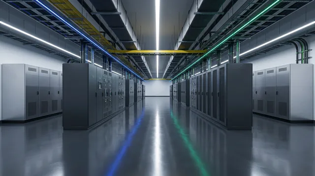
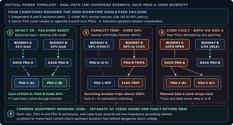
Dual-corded servers survive a single-feed outage only when Path A and Path B stay independent, each side runs below 50% normal load, power cords land on opposite PDUs, and breakers clear faults selectively over one common equipment ground.
Read plain-text walkthrough of this diagram
Panel 1 shows Busway A at 41% and Busway B at 43% feeding Rack PDU-A and Rack PDU-B, with Server PSU-1 on A and PSU-2 on B; losing Path A places 84% on Path B without tripping. Panel 2 shows Busway A at 58% and Busway B at 56%, where losing Path A pushes Path B to 114% and trips the surviving breaker. Panel 3 shows both PSU-1 and PSU-2 mistakenly plugged into PDU-A, dropping the host during planned Side A LOTO work. Callout 4 shows Rack rails and both PDU enclosures bonded to one common Equipment Grounding Bar.
Related courses & interactive lab practice
Facility, rack & safety foundations
Critical power & dual-path feeds
Physical & control-network (OT) security
Shift command, permits & reliability
Practice live readings and switching in "2N Blackout & Live Diesel Synchroscope" with no login required.
Primary standards & technical references