Optical Fiber Inspection, Polarity, and Link-Loss Budget
Plain-English definition
Three practical checks that keep light signals clean and reliable across fiber-optic cables. End-face inspection verifies microscopic connector tips are free of dust or oil before mating. Polarity confirms each transmitter (Tx) connects to the far-end receiver (Rx). A link-loss budget verifies total light loss stays inside transceiver limits.
Why it matters on shift
A tiny dust particle or fingerprint on a 9 micrometer single-mode fiber core blocks light and can crush permanent pits into both glass ferrules when plugged in. Even clean fiber fails to link if Tx faces Tx (reversed polarity) or if dirty patch panels push attenuation past receiver sensitivity.
Illustrative operational example
In an illustrative 500 m single-mode link using ITU-T G.652 and G.671 component assumptions, transceivers offer a 6.00 dB optical power budget (-2.0 dBm minimum launch minus -8.0 dBm receiver sensitivity). Four mated LC connector pairs across two patch panels (4 x 0.35 dB = 1.40 dB), two fusion splices (2 x 0.10 dB = 0.20 dB), and 0.5 km of fiber (0.5 x 0.40 dB/km = 0.20 dB) total 1.80 dB loss, leaving 4.20 dB margin.
Scope, code & safety boundary
Laser eye safety comes first: invisible infrared light from live fibers or transceivers can injure eyes without triggering a blink reflex, so never look into a fiber end or unfiltered scope; always use a digital video probe. Inspect, dry-clean if needed, and re-inspect even new jumpers under IEC 61300-3-35, and check receiver overload limits on short high-power runs. Dedicated optical craft and multi-fiber push-on (MPO) polarity labs belong to the planned Rack and Fiber Craft candidate course (not published).

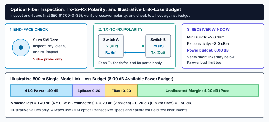
Reliable optical links require clean 9 micrometer cores verified with a video probe (IEC 61300-3-35), crossover polarity connecting each transmitter (Tx) to the far-end receiver (Rx), and total connector, splice, and cable loss within the transceiver power budget.
Read plain-text walkthrough of this diagram
Three-stage optical check plus stacked loss bar. Stage 1 shows a 9 micrometer single-mode fiber core inspected, dry-cleaned, and re-inspected with a digital video probe only (never an unfiltered eye scope). Stage 2 shows Switch A Tx feeding Switch B Rx and Switch B Tx feeding Switch A Rx. Stage 3 shows an illustrative 6.00 dB power budget (-2.0 dBm minimum launch minus -8.0 dBm receiver sensitivity) with a reminder to verify receiver overload limits on short links. Bottom bar sums 4 mated LC connector pairs (1.40 dB), 2 fusion splices (0.20 dB), and 0.5 km single-mode fiber (0.20 dB) to 1.80 dB modeled loss, leaving 4.20 dB unallocated margin.
Related courses & interactive lab practice
High-density AI cooling & commissioning
Physical & control-network (OT) security
Practice live readings and switching in "NOC, Spine-Fiber & White-Space Walkdown" with no login required.
Primary standards & technical references